Part 3
I think I have too much time on my hands to think and not enough time for the doing!
DLG, glider, DLG, glider - I already know this plane will weigh more than your average DLG so I started toying with the idea to make a V tail since it will be hand launched with the prop spinning!


To recap - I decided to make a laminated wing rather than folded (scratch build style) and I was getting ready to use the fibreglass on it! It went pretty well for a first timer other than selecting the wrong carbon fibre strip causing a step in the surface that needed serious sanding. Sanding was OK but I ended up with some contamination giving a dirty appearance. Otherwise, the Wing is pretty straight and stiff! I was pretty impressed at how smoothly it went next time I'll try C/F instead of glass!
The glassed wing weighs in at about 280 grams (9.88 oz) without sanding, filling and painting and seems light to me!
Sadly the first fuse that I made by RPs went out of shape, so I had a rethink, got busy on CAD, and then remade them with the front designed to plug onto the back half, with a tongue from the back half protruding into the front half to support the battery and Rx. Well, that's the theory!
At the same time, I decided the wing join and mount at the centre was a bit rough so I cut the wing down the middle and designed a new centre joiner/wing mount that provides the dihedral and allowed me to cut the wings square.

 Next, using sandpaper wrapped around the tapered boom I roughed up the fuse's (internal) taper, epoxyed the boom, and cut it to 60cm. I think I am getting wedded to the idea of a V tail!

 Next, I started the process of painting the wing and the fuse and like with any paint job the top coat is only as good as the undercoat, so there is plenty of work ahead to tidy the wings given the issue I had with the wrong carbon tape strips. Nevertheless, it will all come out in the wash, and the second wing at some stage will have the benefit of lessons learned!

 The motor mount was a tad wide and I just managed to squeeze in the bolts and trim the edges so the cowl will fit. The motor mount is bolted from the inside with some epoxy on the thread to keep the nuts on! Next time I would make some internal bosses and screw directly from the front.
 Today I made some good progress on the wings, the painting is getting there, so I decided to cut the Ailerons free of the wing in preparation for attaching them with a silicone hinge.
Cutting through the wing exposed the internal foam so I put some epoxy along the edges to give the silicone something to stick to. A bit more sanding and painting and they should be good to go! I'm going for a matt charcoal grey finish with some yellow fluoro somewhere underneath.
I was surprised how many blades I used to cut through the fibreglass even though there is only one layer of very fine glass on each surface.
I cut the ailerons out on an angle, and my plan is to swap the left for the right which will bring the ailerons together with the wing creating a V between them for the hinge. My trailing edge is a tad thick so that will also go on the list for the second wing build!


My plan was to make a silicone hinge but it was a disaster, the tape on the back side was not sticky enough to prevent migration of the silicone underneath the tape, and the goop in the V was a nightmare to smooth. I gave up and wiped off all the silicone with turpentine.
I jumped online and was looking at the CA hinges again, as it was time for another plan! Sadly its the weekend and I was impatient to get this done so I searched the garage for something flexible. In the end, I had an epiphany to use small cable ties cut into pieces. Using a cold chisel I dented the middle to thin them out even further, and there was an added bonus with the teeth allowing for better glueing.
I first marked and set the hinge positions with a small nail pushed into the foam followed by a drill large enough to match the hinge size. Next, I glued the hinges into the wing side with 5min epoxy, then assembled the aileron onto hinges to finish. There is a little resistance in the aileron but it does not feel restrictive, and once the servos are in place we will see! If they need to be tweaked I will file them a bit or touch them with the tip of a soldering iron!
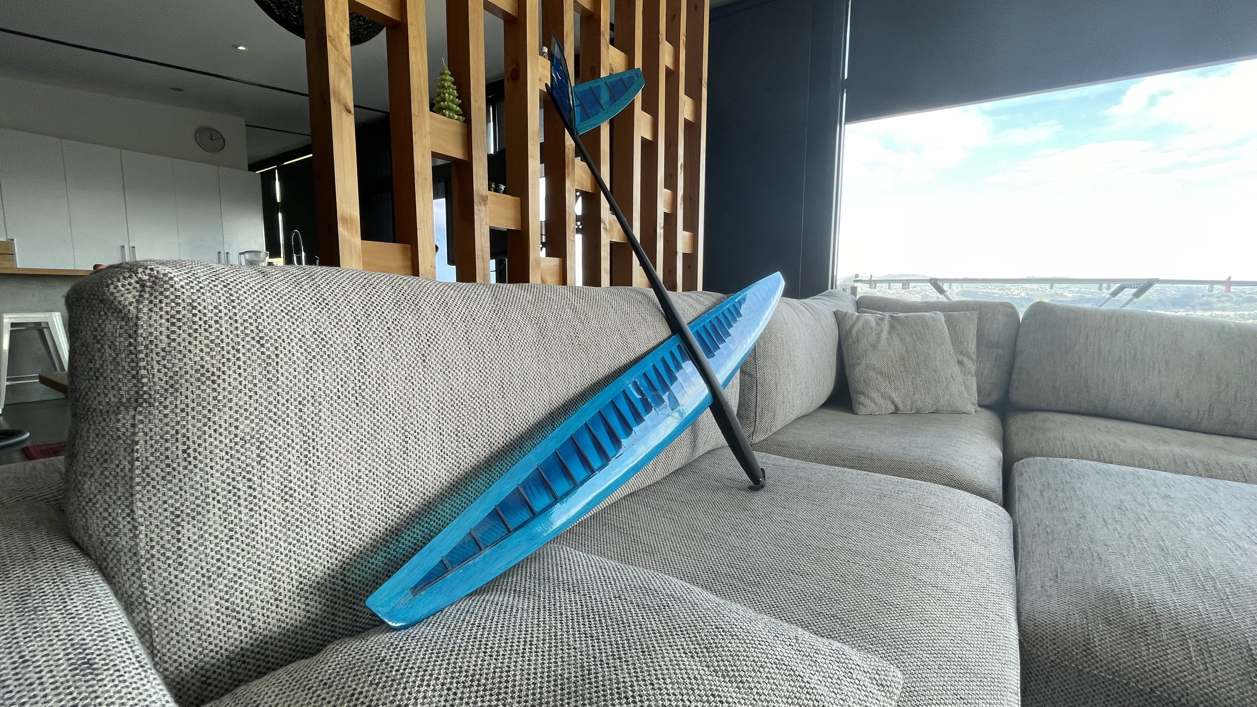
The wing halves are not too bad if I have to say so myself - time to join them together!


In the meantime I have made a concept for finishing the graphics - I am going for a hi-viz camo on the top of the wing only. I printed the design on the photocopier to use as a template for masking and painting. Planning to use spray cans and it's probably wise I sort them one wing at the time before the joining!

A bit of post-Christmas build action today and the closer I get to the finish line the further away it all seems. My last build with foam and tape took a few hours compared to this one which is taking weeks! This build is getting a bit out of control!
Painting the wing graphics went reasonably well, masking tape cut from my templates then transferred to the wing is a pretty easy process, but I did get a bit of bleed that needs to be sorted at some point.
The wings are joined to my centre mount which also locates the 4mm bolts that connect the wing to the fuse. I chose to epoxy the bolts in place and slot two of the holes in the fuse mount to make assembly possible.


I ended up going with the hi-viz orange dazzle (rather than red) on the other side of the wing then joined the two halves with my RP'd centre mount. Keeping everything neat is a challenge and with each small mistake, I realise how hard this all is! 


With the wing dry mounted to the fuse, it’s all taking shape and the total weight so far is 600g (21oz) so hopefully, I can keep it under 800g with the motor and electrics!
I just need a damn tail now!


Well, I decided to use the Bixler 2 spare part tail I bought a while back to make the 'V' tail. I'm thinking it will be light and a simple way to try out the tail design without too much effort and if it goes wrong I can live with it!
I borrowed the basic tail design from the SKUA 1.5m 'V' tail but opted for 110 deg in the 'V' instead of the 105 deg in the plan. The SKUA has similar overall dimensions as my glider so the sizing should be OK! The tail will be a bit fatter at about 15mm, so I hope 'Crafty Dan' is right that it will help me fly slow!
Essentially I sliced and diced to get the basic shape and hot glued the two halves together! The foam seems to be OK with high build spray filler so I think I will be able to shape the leading edges quite well in the next stage!
Cable tie hinges fitted using the same technique I previously used on the main wing. Given the tail is EPS foam I just used a small Philips screwdriver to make the holes.
Time to trim the edges and clean them up for painting and they then glue to the CF tail boom.


Finally got to put the whole assembly together - time to put some servos in this puppy! I realise this has a few RP parts and c/f tail boom but I have to kick myself that the wing is made of foam board, and the tail came up pretty sweet from the Bixler spare part tail!
Hopefully with the servos in I can balance out the c/g with the motor and battery up front! I was considering a pull-pull system for the tail, but I think I will stick with a wire from 'up-front' to 'down-back' inside the tail boom.


I ordered some new servos, servo extensions, control horns, and pushrods - I really want to be a bit more precise this time!
Once I had the control horns in place I had an epiphany to rig up two push rods centred by four-way servo head with the main pushrod threaded to maintain alignment. I added a loop of wire at the front of the tail to prevent the pushrod wire flexing when pushing. I decided to put the control horns on top so I could use standard parts and angle the horns towards each other.
Works pretty well! A bit of touchup paint and it will be sweet!

At this point, the tail is not connected to the front servo. The motor is fitted but the leads are too short to get the ESC on and off the motor so ill need to make a couple of extensions but otherwise, it is looking good!

 Time for the servos in the wing for the ailerons - separate servos for each side. I have opted for the same control horns as the V tail, and although not fully hidden the servos should do the job. Cutting through the fibreglass was easy, but my-my the carbon fibre tape was tough on the knife blades!
The servos were hot glued in once push rods and the clevises were adjusted roughly. The final trim can be tuned with the clevises in tandem with the digital trims.
I decided to make a shelf to locate the elevator servo with space beside it for the Rx. if I can get these two components out the way it will be easier to balance the CG with the battery and ESC.


I'm using the FS i6s TX and Rx and the antennas are quite large. This is my plan for arranging the gear but I am not sure the best way to get the antennas at 90 deg - so I need to think on that!
It was a bit of a mission to get the elevator control rod connected to the servo and glued in. Luckily I could release the split connectors to the elevator at the rear and slide the whole assembly forward enough to attach the servo to the control rod, then a dab of hot glue, an alignment check and it was in!
The control rod travels on an arc from the servo to elevators so at the midpoint of the arc I added a pin to prevent the rod straightening when pulling and the bench testing went well.
The power pod looks especially nice!


Sadly down at the field, I could not get the Tx and Rx working - I headed home with my tail between my legs! As it turned out I had made a rookie mistake and had plugged the ESC into channel 4 instead of channel 3!
Luckily it was a tad windy so at least I can try again on a calmer day!

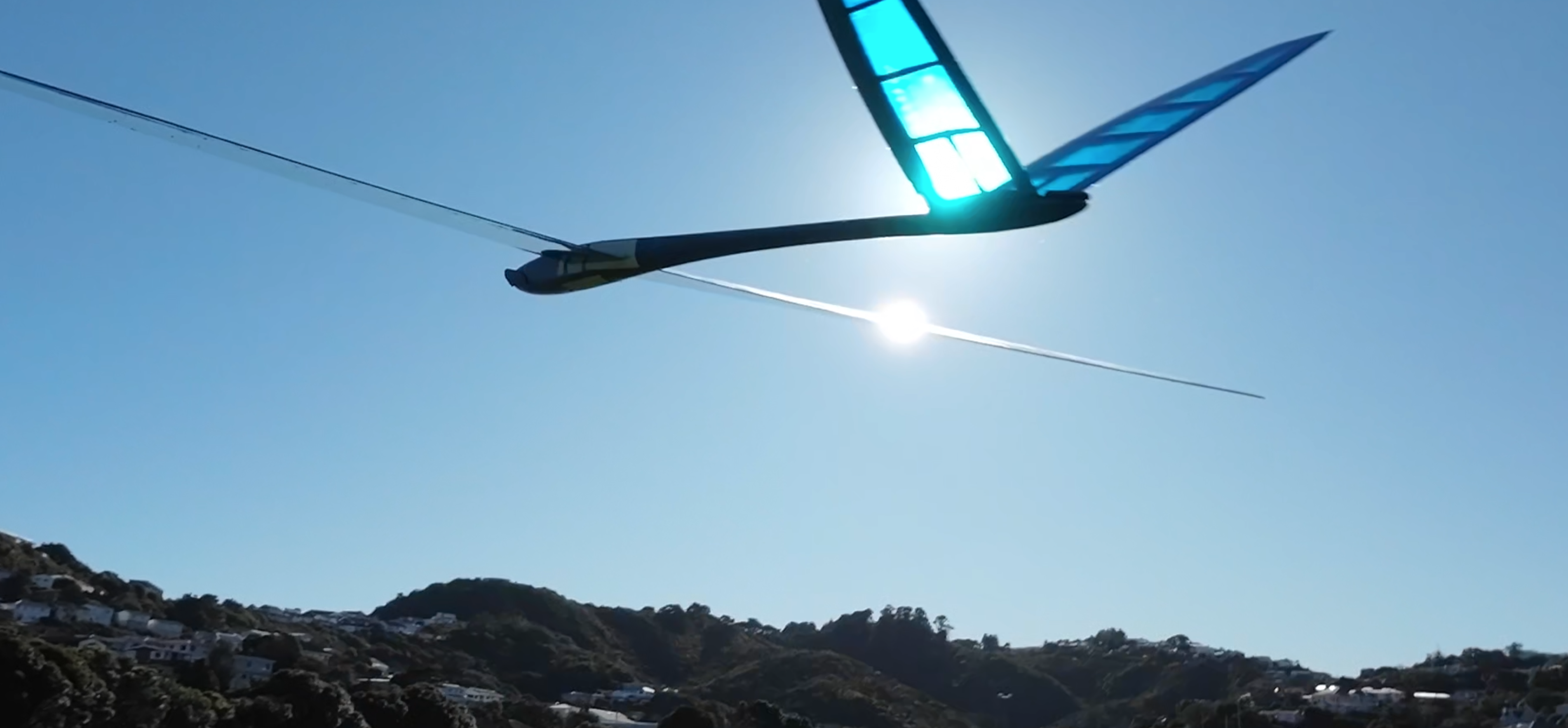
I'm quite excited with the result as my previous builds have been more traditional FT style. I need to thrash the trainer a bit more to get some flying confidence, but I will maiden the Vista regardless!
The glider on the left is a hotliner I bought 15 years ago and has been hanging on the wall ever since, so the dream is to step towards being able to navigate it at its +200kph capability

It has been a long road from these simple builds to where I am today…
 Pitcheron


Log In to reply
Log In to reply
Log In to reply
If you would here is my email louisonline@websitepro.co.za
Log In to reply
Log In to reply
Log In to reply
Log In to reply
Log In to reply
These days I use printed parts for moulds to make carbon fuselages and am building around 300g for 1.5m wings..
Log In to reply